T.O.B.B. is my attempt in building a two wheeled balancing robot (inverted pendulum). It was inspired by nBot from David P. Anderson.
(http://www.geology.smu.edu/~dpa-www/robo/nbot/).
When I first saw videos of nBot I instantly knew that this is a must have toy. It took me some time to really get started with it. My first contat with microcontrollers was the PIC. The more I worked with it, the more I learned to hate it. This went up to the point that I stoped playing with electronics at all. Two years later I gave the AVR (Atmega16) a try and instantly fell in love with it. It is ridicuously easy to program ("C") and can even be debugged through JTAG. All that for a few €. T.O.B.B. is my second AVR project (The first was evertool, a excellent AVR programmer). My PCB's are still a bit clumsy (I've never really done that before) and sport some greenwire, but they work.
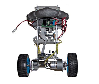
The current implementation of T.O.B.B. is roughly 35cm high and weights ~2.5kg. It is controlled by two homemade Atmega16 boards.
IMU with ADXL322 accelerometer and ADXRS401 gyroscope
Motorcontroler with L298 H-bridge
The boards are programmed in C using the gcc AVR crosscompiler under Linux. Communication between the boards is implemented with a I2C bus. I'm not completely happy with the I2C bus but it works for the moment.
T.O.B.B. is driven by two 12V (~4Watt) motors with a gear ratio of 1:50. This was a bad idea, as the motors are too slow to handle more than roughly 2° of tilt. I already ordered two 10W motors with a gear ratio of 1:18 which hopefully will work better. The motors are powered by two 7.2V/1.7Ah NiCd battery packs.
One of the first balancing attempts. Actually is is the second attempt. When I first switched it on, to my own surprise it was standing more or less like a charm (see video). I went to my daughters room (as she was a non believer :) and showed it to her. She made this movie to record this historical event :-)
T.O.B.B. has no wheel encoders yet. The controll loop is a simple P-loop. The mechanical system shows a strong lowpass behaviour (the batteries are on top yielding a high rotational inertial moment). That's probably why it works. The next thing is to improve the drive mechanism. There is a lot of play in the gears (nBot style motor configuration). The next version will have belts which should work better (My mechanical skills are close to 0. Building something with enough precision needed to match two gears is probably beyond my capabilities).
IMU
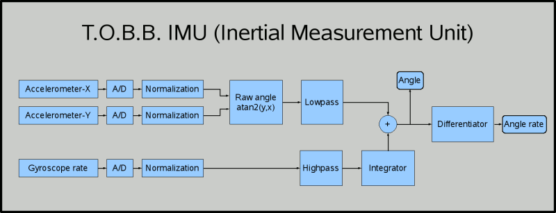
The IMU is a I2C slave. At a rate of 200Hz it provides absolute angle and angle rate as 16bit fixed point values with 0.01°, 0.01°/s resolution. I investigated into Kalmann filtering but ended up with a simple compimentary filter which works quite well. The complimentary filter consists of two first order IIR filters. One lowpass with a cutoff frequency of 0.25% nyquist for the accelerometer and a highpass with the same cutoff frequency for the gyroscope. The sum of the step responses is the step (which is what we are looking for). All calculations are performed with straight forward floating point implementations. The Atmega16 runs at 16MHz and is more than fast enough for that purpose.
Diagram of the filter structure used for the IMU
//=======================================
// Recursive complimentary filter
// Transition frequency at 0.25%
// nyquist frequency.
//---------------------------------------
// Copyright 2008 Matthias Toussaint
// Usable under the terms of the GPL 2.0
//=======================================
// Filter 'object' definition
//typedef struct{float hp_x0, hp_x1;
float hp_y0;
float lp_x0, lp_x1;
float lp_y0;
float hp_last;
float hp_int;
} CompFilter;
// very simple complimentary filter
// (0.25% nyquist hp-lp combination)
//float comp_filter_step( CompFilter *filter,
float angle,
float rate );
I'm not afraid of SMD soldering, but BGA packages (like the gyroscope) are not very hobbyist friendly. For that reason I bought header boards from Sparkfun for the accelerometer and the gyroscope. The accelerometer (ADXL322) and gyroscope (ADXRS401) outputs are sampled at a sample rate of 200Hz and fed into the filter structure depicted above. At the output I get the absolute tilt angle and the tilt angle rate with an update rate of 200Hz. If I understand the datasheet correctly, the gyroscope has been programmed for a bandwidth of 400Hz by Sparkfun. So I'm actually undersampling a lot here. Maybe I should change C4 on the header board to something like 10nF to be on the safe side. Anyone with experience on that? The accelerometer seems to be programmed for 50Hz bandwidth, which would be ok.
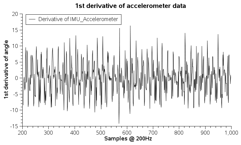
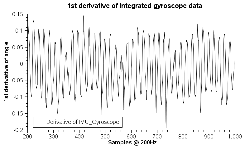
The integrator is implemented using the trapezoidal rule and the differentiator is a deriving Savitzky-Golay FIR filter with 7 taps (coefficients: -0.1071429, -0.0714286, -0.0357143, 0.0, 0.0357143, 0.0714286, 0.1071429) to improve SNR for this sensitive measurement.
Tests showed that the standard deviation (IMU laying flat on the table) for the filtered angle is something around 0.07° and for the angle rate ~0.5°/s (within a time interval of 2.5s)- I have no idea if that is good or bad, but it seems to be sufficient for my purpose.
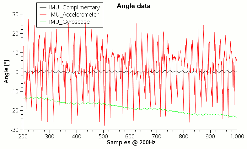
The plot above shows some raw data from the IMU while T.O.B.B. was balancing. The drift of the integrated gyro data can easily be seen. It is also obvious that the output of the complimentary filter is a lot smoother than the data from the accelerometer. That's why you can't use a gyro or an accelerometer alone for balancing.
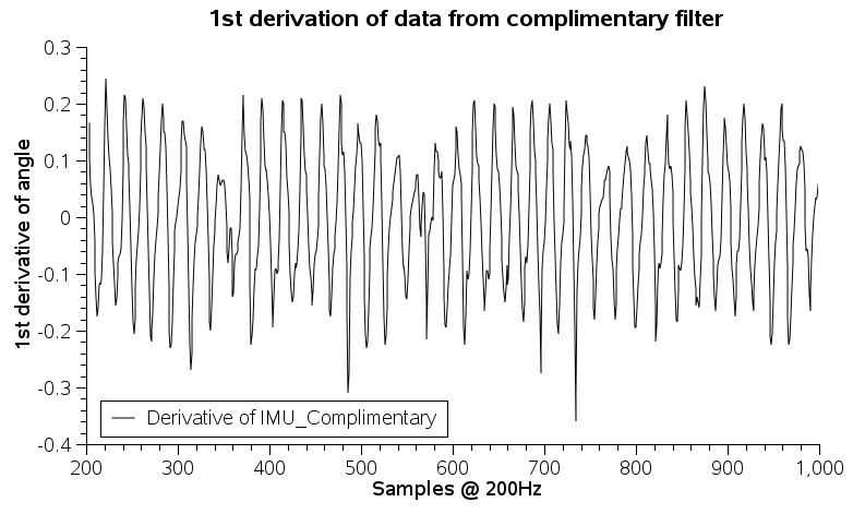
The following three plots show the first derivative of the respective measurement. This corresponds to the angle rate. It clearly shows that the variance in the combined output is quite close to the "better" sensor.
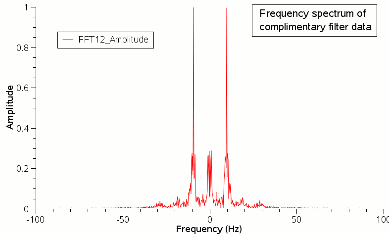
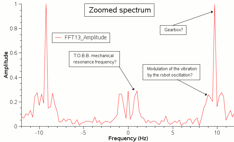
The last plot shows the spectrum of the complimentary filter output. I'm not 100% sure how to interpret the data, but I believe that T.O.B.B. has a mechanical resonance frequency of ~1Hz and the gearbox seems to introduce strong vibrations around 10Hz. What do you think?
Motorcontroller
Not much to say about the motorcontroller. It drives the motors with a L298 H-bridge using OC1A/B for a PWM with approx 3kHz.The motor controller is a I2C master and polls the current angle from the IMU board with 200Hz (I know, it should be 400Hz). The angle goes into a proportinal control loop to calculate the motor power for the wheels. If the constant for the control loop is too big T.O.B.B. oscillates a lot. If too small it drifts around. If it is way to small it drifts and eventually falls over.